
Welcome to the world’s sixth largest steel plant.
Located at Toranagallu village in the Ballari-Hospete iron ore belt of India, the 10,000-acre, fully integrated Vijayanagar steelworks of Jindal Steel Works (JSW) is the largest single location steel-producing facility in India with a capacity of 12 MTPA. With cutting-edge technology and constant innovation, it has emerged as the world’s sixth-largest steel plant with one of the most efficient conversion costs globally.
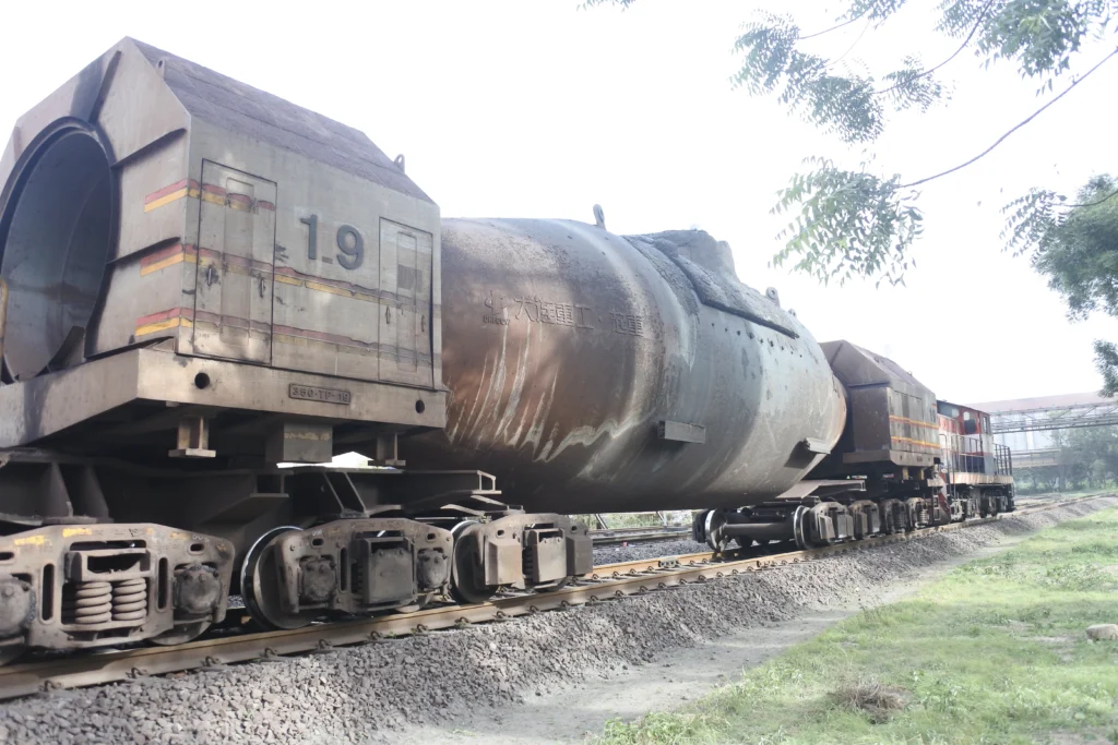
Torpedo attached to the Locomotive, for carrying the molten steel
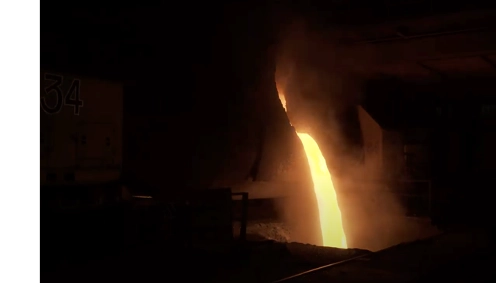
Liquid (Molten) Steel
JSW maintains an internal rail network for transferring molten steel from blast furnaces to various locations. Typically, 300-400 tonnes of liquid steel are carried in special purpose vehicles (Torpedoes) each day. Over the years, the Vijayanagar plant has become a strategic first-mover, embracing new technologies and evolving rapidly in terms of speed and quality. JSW has one of the largest railway sidings in the country at Torangallu. However, over the years, it had certain pain points in the management of its yard, which are as under :
SMS #2 Yard
JSW has commissioned our innovative, pathbreaking, one of its kind Cyber Signalling System at its SMS#2 yard of the railway siding. The SMS #2 yard at JSW has three incoming tracks and four unloading platforms. Nine turnouts (points), numbered 126A to 130, enable a vehicle entering the yard from any of the three tracks, to reach any of the four unloading platforms
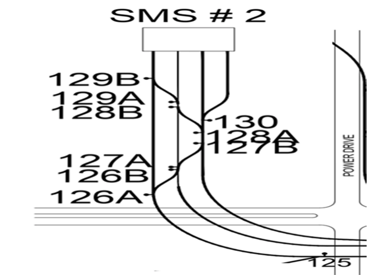
SMS #2 Yard at JSW Vijayanagar Works
How did we execute the project?
First, we had extensive discussions with the Management and operational staff to understand their requirements. Then, with a goal to configure and personalize a Cyber Signalling system that makes SMS #2 yard management easier and more efficient, we have planned a suitable solution tailormade to the specific requirements of JSW. The broad steps of the project execution are as under:
Digital Map
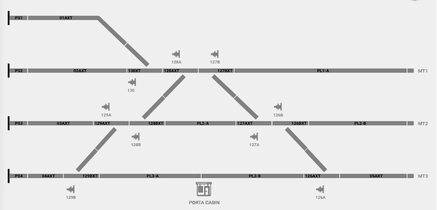
Digital Map of SMS #2 Yard of JSW Steel Vijayanagara Works
As a first step, a Digital Map of the SMS #2 yard was prepared and stored in the central server. The yard was divided into the following ‘functional’ sections that were identified in the Digital Map:
Detection Points
The sections are separated by Detection Points (DP). The detection points are made up of a pair of Fibre Bragg Grating (FBG) Sensors that provide information regarding the wheels moving over them. This information is used by the DPU to obtain Axle Count and decide how many axles have entered the section.
Interactive web-based GUI (Siding Control Center)
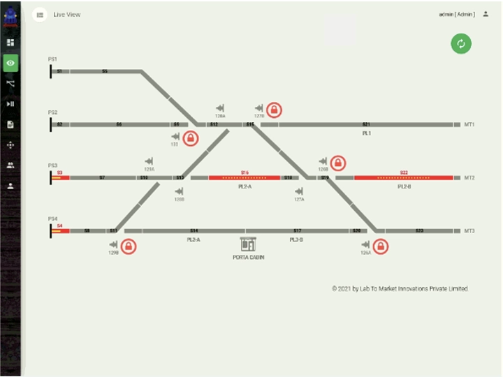
The number of axles in any section of the SMS #2 yard is graphically shown on the GUI with yellow dots. This interactive web-based GUI provides the live status of the yard and the movement of all trains can be tracked in the GUI. All the authorized users are provided with a username and password to view the yard information. Different levels of permissions restrict users to execute only those actions which they are authorized to perform. For example, the Point Machine Operators can only operate the point machines from the GUI to change the route from Normal to Reverse and vice versa.
Remote operation of Point Machines
The current point machine mode and state can be observed in the GUI. Modes of the point machines are MANUAL and AUTOMATE. The point machine states are NORMAL, REVERSE (and FAULT). In the automated mode, a points man can switch a point from NORMAL to REVERSE state (and vice versa) with the GUI from within the engine, without having to stop the train movement. To ensure safe movement over a turnout, the points man can LOCK the point with the GUI. In case the turnout state and direction of train movement are such as to cause Trail Through, the system sounds an alarm to alert the driver.
Train movement: View the train as it moves
The live movement of a locomotive & train across the yard can be viewed by the Authorised Personnel by sitting in the comforts of their office. The train movement can be seen on the screen as it moves from one section to the other. We can see that a particular section becomes clear as the train moves out of that section; and the adjacent sections get occupied, as the train moves in. We can also view the point position. The graphic user interphase (GUI) also shows the direction in which the point is set on the track.
JSW’s own Secure Private Cloud
The solution is designed to be completely wireless and all the data is stored on a private cloud to provide real-time information to the authorised personnel. All the subsystems are connected to the cloud through the high-speed Wi-Fi Radio Access Network (RAN). All the data is stored in the private cloud situated in the place as the railway siding. It is owned, managed, and operated exclusively by JSW, and it exists on its premises.
Yard Information
The yard information includes the section status and the point machine status as shown in the figure. At any time, the state of a section could be CLEAR, OCCUPIED, or ERROR. The corresponding colours used to indicate the section status in the GUI are grey, red, and yellow, respectively.
The history of the train movements with the yard can be obtained using the playback feature provided in the GUI. Authorized persons can view remotely not only the live status of the yard but past train movements, point machine status, number of train movements, section status, etc.
The yard information for the day and for the month can be obtained from the yard performance page in GUI. As shown in the figure, trains/torpedoes per day, longer waiting time are displayed on each day of the selected month. On selecting any particular date, the train movements can be obtained of the same day as shown in the figure.
Yard Information of SMS #2
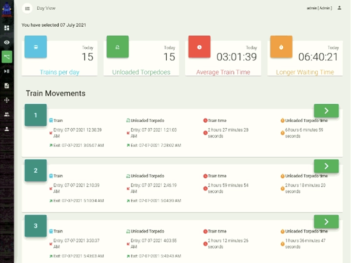
Yard Performance – Day View

Yard Performance –Month View
Reports
The yard utilization statistics can be obtained from the reports in the GUI to know the track utilization, statistics on the unloaded torpedoes, entry/exit of the train movements and the number of point machine operations. Sample screenshots of the reports generated for the SMS-2 yard are as shown in the following figures.
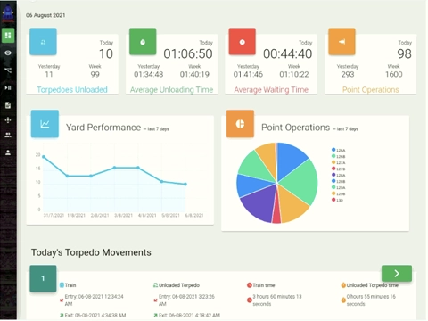
Dash Board of GUI
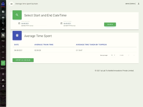
Report – Average Time Spent by trains
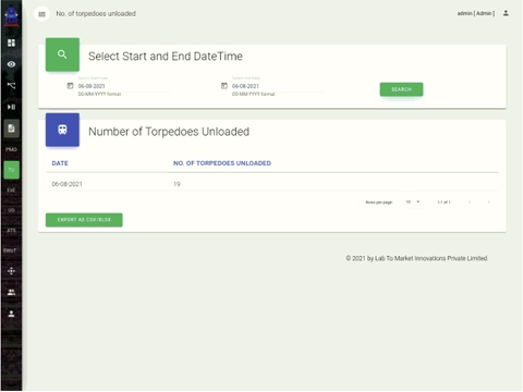
Report – Number of torpedoes unloaded
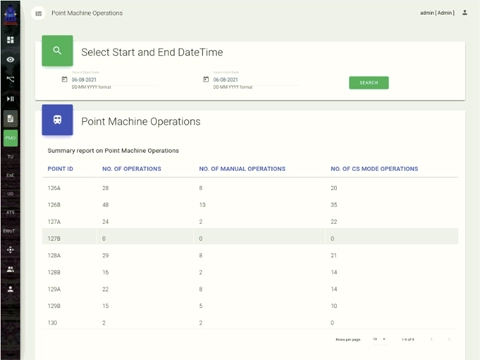
Report – Point machine operations
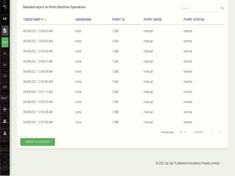
Report – Point machine operations
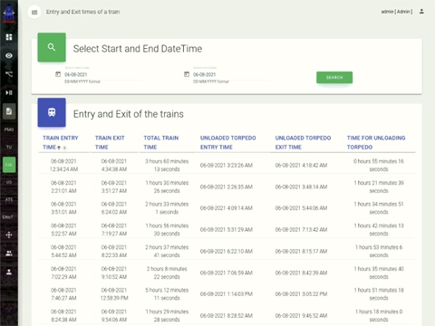
Report – Entry/Exit of the train movements
The current day’s train movement can be viewed in the dashboard of the GUI. The dashboard shows the statistics of torpedoes unloaded, unloading time, waiting time and the point machine operations count. The graphical representation of the number of torpedoes unloaded and the number of point machine operations of all the 9 points are as shown in the report in the figure. The train movements are displayed with the entry/exit of the train and torpedoes with the total train time in the yard.
Our Cyber Signalling System Commissioned at JSW Vijayanagar Works
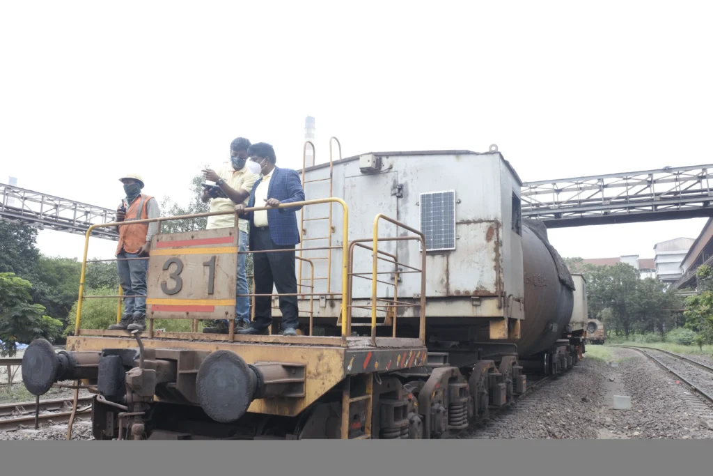
Mr. GS Rao, MD & CEO inspecting the Cyber Signalling System at JSW Plant
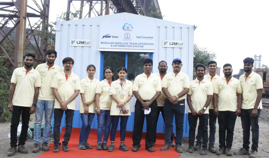
Team L2M Rail at the site of JSW Vijayanagar Works
L2M Rail offered its novel Cyber Signalling System to address the pain points and requirements of JSW. Certain additional features are also provided that JSW management found useful. Our solution provides the following services:
An interactive web-based Graphical User Interface (GUI) pertaining to point and yard status in HMI:
Point machine and yard status are displayed in the GUI on the handheld device. Each point machine status, that is whether it is normal or reverse, and yard information such as which line is occupied, whether torpedo is loaded or not etc., can be seen on the GUI.
Operation of individual points using HMI:
The direction of visual turnouts (points) can be observed and changed from the HMI wirelessly after selecting the concerned point machine. All authorized personnel (loco drivers/ points men/ yardmaster) shall be provided with a user ID and password and all authorized users shall be able to operate the points or obtain yard information.
Caution on possible Trail through:
The loco pilot shall be cautioned if the locomotive is moving towards a turnout that is not in the right position for the desired train movement.
Yard utilization statistics with respect to past/current movements of the train(s):
Historical data with respect to Locomotive/Torpedo movement shall be stored on the edge device (DPU). When required, this data can be transferred to a hard drive and used for performance analysis.
Monitoring the movement of Locomotive/Torpedo while entering/exiting the yard:
Sensors attached to the rails shall detect the direction of Loco/Torpedo movement. Track occupancy information shall be furnished based on the axle counts.
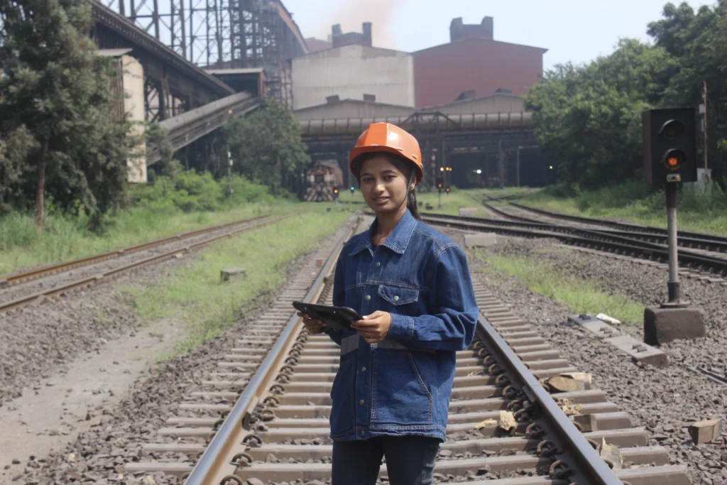
Site Engineer remotely operating the Point Machine using the Hand Held Devise
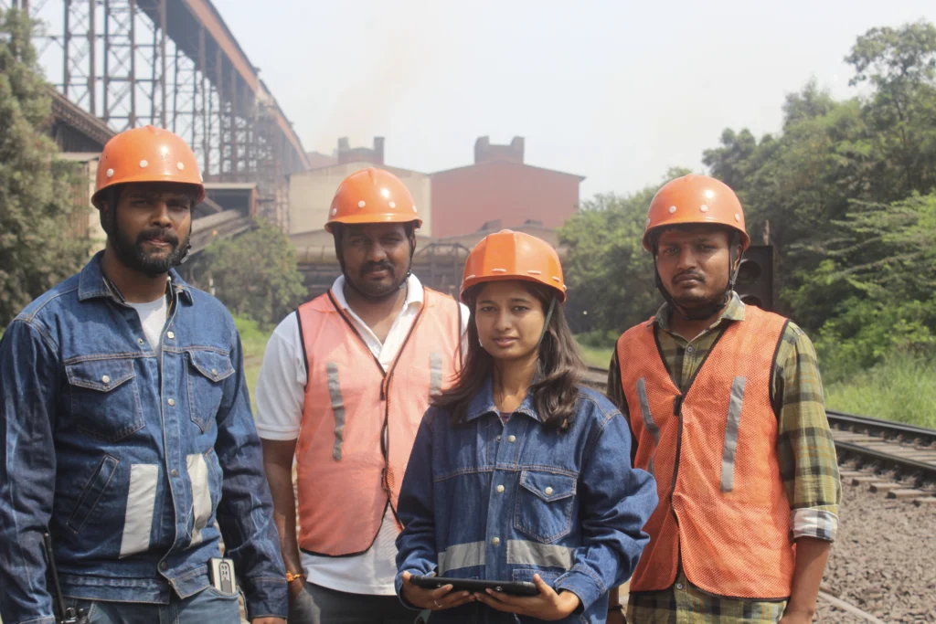
Operations Team at the Site
Loaded or unloaded Torpedo detection:
A loaded torpedo causes more strain on the rail compared to an unloaded Torpedo. Depending on the strain difference torpedo status can be indicated.
Information regarding Torpedo entry and exit from the yard in Real Time:
After obtaining axle count and direction of Loco/Torpedo movements, the entry and exit events shall be recorded and displayed.
Real-Time Information on the movement of Train/Torpedo:
As each axle passes over the FBG sensors the data is captured by the interrogator and communicated to DPU. Proprietary L2M algorithms are used to count the axles in real-time and displayed on the GUI.
The alternative mode of point operations:
In order to ensure uninterrupted movement of Torpedo, Cyber Signalling System includes the following alternative modes of point operation: