AN APPARATUS, METHOD, AND SYSTEM FOR CYBER SIGNALLING AND TRAIN TRAFFIC CONTROL AT RAILWAY YARD
Cyber Signalling Patent granted to L2M Rail
Date of Filing: 28 May 2020
Date of Grant: 23 July 2021
Patent duration: 20 years from 28 May 2020
ABSTRACT
The invention discloses an apparatus, system, and method for real-time managing of trains’ traffic in the railway yard. An embodiment of the present invention comprises a plurality of FBG sensors, local control unit (LCU), control unit (CU), and communication network. The local control unit (LCU) calculates the number of train axles on detection points (DP) in a point and point zone status information to the control unit (CU). The control unit (CU) compares the number of train axles of two or more detection points (DP) to find track occupancy and point zone status. The Human Machine Interface (HMI) device of users displays the track and point zone status. The authorized users of HMI devices can operate specific point machines (PM) for train route setting and computerized signalling. The system and method improve safety and efficiency of trains operation at the railway yard.
BACKGROUND
Signalling and train control includes route settings and point machine operation to divert the train to the desired route. Usually, the point machine at railway yards are operated manually and the operations staff do not have first-hand information on track occupancy. The track information has to be obtained by visually inspecting the railway tracks. The driver of the train is accompanied by a helper. The duty of the helper is to step out from the train at each point and manually operate the point by pressing an electric button. There is no real-time information on locomotives/wagons.
Conventional signalling and train operation control systems create complexity in the yard and delay the movement of locomotives due to route interlocking and long clearance time. In addition, when the points are operated manually more man power is required and efficiency is reduced. It is also prone to human error during operation. In addition, lack of information to the site supervisors and managers who are away from the location and are ignorant about the actual scenarios at the site. Such a lack of information in real-time is a major barrier in managing railway yards using conventional signalling systems.
Our invention overcomes all the problems associated with conventional signalling and provides a highly safe, user-friendly, modular, customizable, next-generation signalling system for the management of railyards and high-speed railway. Our patented CS System is a computerized solution for signalling, route setting, and managing locomotives/wagons in the rail yard with the availability of data for analytics/replay and better asset utilization.
SYSTEM ARCHITECTURE
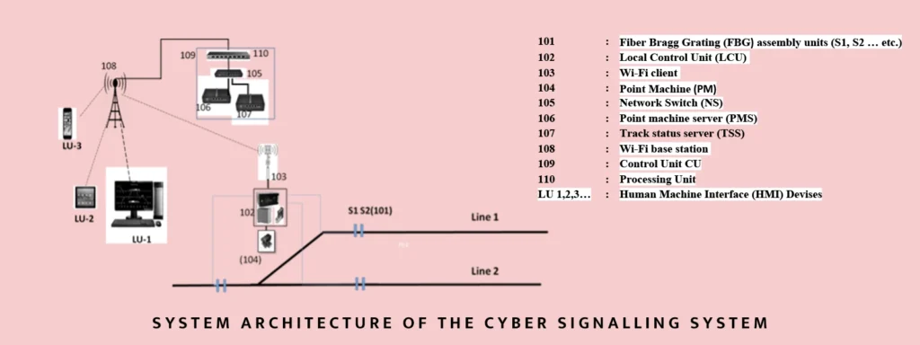
System Architecture
The system architecture comprises FBG sensors assembly units (S1-S6) 101, coupled with a Local control unit (LCU) 102, Wi-Fi client 103, Point Machine (PM) 104, control unit (CU) 109, and Wi-Fi Base station 108. Further, LCU 102 includes an optoelectronic instrument, data processing unit (DPU), PLCs, Relays, and Ethernet Switch with Wi-Fi client 103. The system also includes a central unit (CU) 109 with network switch (NS) 105, Point machine server (PMS) 106, Track status server (TSS) 107 with Wi-Fi base station 108. The control unit (CU) 109 with servers (106,107), processing unit 110 and network switch (NS) 105 is connected with Wi-Fi base station 108. Processing unit 110 in the control unit (CU) 109 compares the number of axles of every DP of point zones to detect track occupancy and store data in the database of track status server 107.
OBJECTIVES OF THE INVENTION
SUMMARY OF THE PATENT
Aspects of the present disclosure relate to strain-based devices and systems for computerized signalling and real-time train traffic control using Fiber Bragg Grating (FBG) assembly unit or FBG packaged strain sensor. The FBG assembly unit is connected to the Local Control Unit (LCU) which is near every point zone to count train axles and point zone status. LCU also drives point machines for desired route setting of the train. LCU communicates axle count information near the detection point of the point zone to Control Unit (CU) through a communication network. The processor in Control Unit (CU) compares the number of axle counts at point zones to detect track occupancy. Control Unit (CU) also store track status and point zone status information. The real-time yard status is displayed on Human Machine Interface (HMI) devices. The HMI devices also instruct CU to communicate with LCU to drive point machines. However, status information is not limited to the track occupancy and points positions, among other like information.
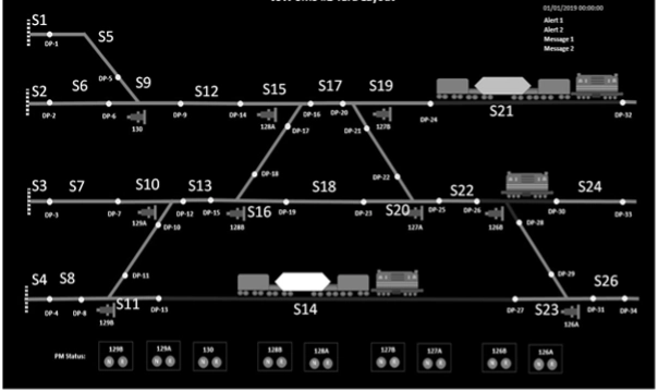
Railway yard layout in accordance with an embodiment of our Innovation
The Fiber Bragg Grating (FBG) sensor of our innovation is highly sensitive, simple, compact, easy, and widely deployable even in a logistically difficult environment. Our innovation also provides for a method and system for deployment of FBG sensor with metal protective casing housing clamp called as FBG assembly unit, mounted under the rail in middle between two sleepers.
The FBG assembly unit is connected with a programmable optoelectronic instrument using armored fiber optical cable to interrogate reflected optical signals with a Bragg wavelength. When the train passes over the rail, the track gets strain and the FBG sensors cause a shift in Bragg wavelength. The optoelectronic instrument computes the wavelength shift due to strain and communicates this information to Data Processing Unit (DPU). DPU in the local unit calculates the number of train axles at detection points (DP) of a point zone.
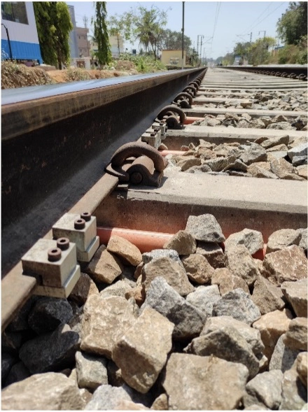
Clamps holding FBG sensors in a protective casing housing in accordance with an embodiment of the present disclosure
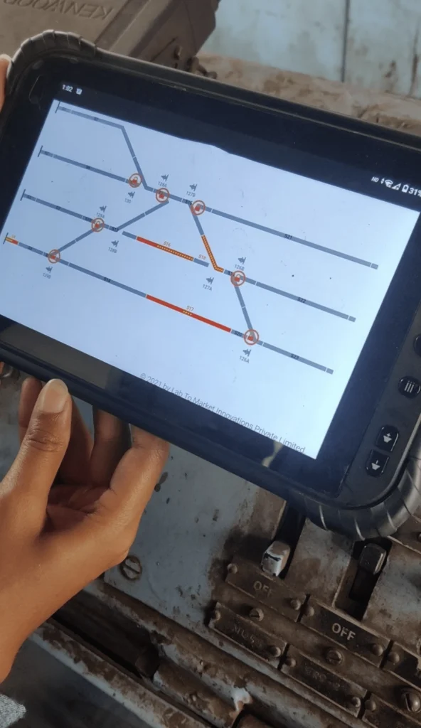
Train movement on HMI devise as per the disclosure in the Patent
The authorized users of HMI device (loco driver or any authorized person) with user ID and password can monitor the current rail yard status wirelessly and can manage the operation of the train by selecting the position (Normal/Reverse) of the point machine (PM) with their HMI device.
Our innovative solution also provides a method for creating an animated video of all trains’ movement on a specific date and time slot and display the video at the desired speed to authorized users. The method includes determining the date and time of train movement, obtaining data from the control unit (CU) in the form of a table, and creating an animated video based on such data table for a display to authorized users.
Our solution includes a feature to switch from wireless mode to manual mode and vice-versa. Our patented invention provides a modular, flexible and real-time solution with computerized signalling and train traffic control at the railway yard using FBG sensors. The system improves asset utilization, increases efficiency, and reduces human error.